👉 Garret's diagram is used to design channels.
👉Garret's diagram is a graphical representation to obtain canal design parameters based on
- Kennedy's Theory
- Kutter's formula
Lacey's design is based on stable channels in alluvium and he assumed some bed load and suspended load.
1. True Regime
2. Initial Regime
3. Final Regime
👉 True Regime: A channel is said to be in regime condition if it is transporting water and sediment in equilibrium such that there is neither silting nor scouring of the channel. But according to Lacey, the channel should satisfy the following conditions to be in regime condition.
- Channel is said to be in initial regime condition when only the bed slope of channel gets affected by silting and scouring and other parameters are independent even in non-silting and non-scouring velocity condition.
- It may be due to the absence of incoherent alluvium.
- According to Lacey’s, regime theory is not applicable to initial regime condition.
- If the channel parameters such as sides, bed slope, depth etc. are changing according to the flow rate and silt grade then it is said to be in final regime condition.
- The channel shape may vary according to silt grade
Step1: Compute Lacey Silt Factor (f)
d = average size of particle in mm
Here V = Velocity of flow in m/sec
Q = Discharge in m3/sec
f = Lacey's silt factor
Step 3: Compute Area of the Channel by using
Q = A.V
Step 4: Compute wetted perimeter (P) of the channel
Here, P is the wetted perimeter in m
Q is the discharge in m3/sec
Step 5: Compute Hydraulic radius (R)
Here R is the hydraulic radius in m
V is the velocity in m/sec
f is the silt factor
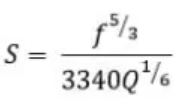
Step 6: Compute Bed slope (S) by Lacey theory as
Note: Lacey Regime Scour depth (R) can be computed as
- Lacey did not explain the properties that govern the alluvial channel.
- In general, flow is different at bed and sides of the channel which requires two different silt factors but Lacey derived only one silt factor.
- The semi-elliptical shape proposed by Lacey as the ideal shape of the channel is not convincing.
- Lacey did not consider the
silt concentration in his equations. - Attrition of silt particles is ignored by Lacey.
- Lacey did not give proper definitions for the silt grade and silt charge.
HAPPY LEARNING
👉 Follow me on talktorashid.blogspot.com


Thank you so much sir
ReplyDeleteToday my exam thank you sir
ReplyDeleteNice Blog. Thanks for sharing with us. Such amazing information.
ReplyDeleteBest Bsc in Computer Science College in Roorkee
Best Bsc in Information Technology College in Roorkee
Best BCA College in Roorkee
Top BBA College in Roorkee
Best MBA College in Roorkee
thank you
ReplyDeleteCivil engineers can work in a number of industries, resulting in fresh challenges and possibilities for learning and advancement. You can also check out about Best Civil Engineering College in Maharashtra here
ReplyDelete