Tuesday, 28 June 2022
Wednesday, 18 May 2022
Important IS Codes in Civil Engineering
👉 IS: 456 – code of practice for plain and reinforced concrete.
👉IS: 383 – specifications for fine and coarse aggregate from natural sources for concrete
👉 IS: 2386 – methods of tests for aggregate for concrete
👉IS: 456; 10262; SP 23 – codes for designing concrete mixes
👉IS: 800:2007-Code of practice for general construction in steel
👉Geotechnical Engineering
- Determination of water content (moisture content) IS:2720 (Part .II) 1973
- Determination of specific gravity of fine-grained soil IS: 2720 (Part. III) 1980 Sect/1
- Determination of specific gravity of fine, medium & coarse-grained soil. IS: 2720 (Part. III) 1980 Sect/2
- Grain size analysis IS:2720 (Part.4) 1985
- Determination of Liquid and plastic limit IS:2720 (Part.5) 1985
- Determination of shrinkage factors IS: 2720 (Part. VI) 1987
- Determination of water content - dry density relation using light compaction. IS: 2720 (Part. VII) 198
- Determination of water content - dry density relation using heavy compaction.IS:2720 (Part.8) 1983
- Determination of Unconfined compressive strength IS: 2720 (Part. X) 1991
- Determination of shear strength parameters(tri-axial) with out measurement of pore pressure parameters IS:2720(Part. XI) 1971
- Direct shear test IS: 2720 (Part. XIII) 1986
- Determination of Density Index (R.D) of cohesionless soil.IS:2720 (Part.14) 1983
- Determination of consolidation properties IS:2720 (Part.15) 1986
- Determination of permeability IS:2720 (Part.17) 1986
- Determination of dry density of soils, in place by the sand replacement method. IS:2720 (Part.28) 1974
- Determination of dry density of soils, in place by the core-cutter method.IS:2720 (Part.29) 1975
- Laboratory vane shear test. IS:2720 (Part.30) 1980
- Determination of the density in place by the ring and water replacement method.IS:2720 (Part.33) 1971
- Determination of free swell index of soils IS: 2720 (Part. XI) 1977
- Measurement of swelling pressure of soils. IS: 2720 (Part. XII) 1978
- Design and construction of pile foundation. IS: 2911:2010
👉 IS codes on Earthquake Resistant Building Design
- Criteria for Earthquake Resistant Design of Structures: IS:1893
- Code of practice for earthquake design resistant design and construction of building. IS:4326
- Improving Earthquake Resistance of Earthen Buildings. IS:13827
👉 Cement
- Specification for 33,43,53 Grade ordinary portland cement IS 269 - 2015
- Specification for Rapid hardening portland cement IS 8041 - 1990
- Specification for portland Pozzolona cement IS 1489 (part 1&2) 1991
- Methods of physical test for hydraulic cement IS 4031 - 1988
- Method of chemical analysis of hydraulic cement IS 4032 - 1985
- Method of sampling for hydraulic cement IS 3535 - 1986
- Standard sand testing of cement IS 650 - 1991
👉Aggregate
- Specification for coarse and fine aggregate IS 383-2016
- Methods of test for aggregate for concrete particle size and shape IS 2386 (Part I) 1963
- Methods of test for aggregate for specific gravity, density, voids, absorption and bulking IS 2386 (Part III) 1963
- Methods of test for aggregate for Mechanical properties. IS 2386 (Part IV) 1963
- Methods of test for aggregate Soundness IS 2386 (Part V) 1963
👉Bricks
- Method of sampling of clay building bricks IS 5454 - 1978
- Method of test for burnt-clay building bricks. IS 3495 (Parts I to iv) 1976
- Common burnt clay building bricks. IS 1077 - 1992
👉 Cement Concrete
- Specification for coarse and fine aggregate. IS 383 - 1970
- Specification for compressive strength, flexural strength IS 516 - 1959
- Code of Practices for plain and reinforced concrete etc. IS 456 – 2000
- Recommended Guide Lines for Concrete Mix Design IS 10262 – 1982
Monday, 16 May 2022
Acceptable Values in Geotechnical Engineering
👉 There is no upper limit of water content (w)
i.e. w ≥ 100%
👉 Void ratio (e) can be greater than unity
e > 1
👉 The value of porosity (η) lies in between 0 to 100%
i.e. 0 < η < 100
👉 Degree of Saturation (S)
0 ≤ S ≤ 100%
👉 Sum of air content (A.C) and degree of saturation (S) should be unity or 100%
i.e. A.C + S = 100% or 1
👉 Comparison between Unit weight of solid (Ys), Saturated unit weight (Ysat), Bulk unit weight (Yb), Dry unit weight (Yd) and Submerged unit weight (Ysub)
Ys > Ysat > Yb > Yd > Ysub
👉Approximate value of Ys, Ysat, Yb, Yd and Ysub
Ysub ⋍ 10 kN/m^3
Yd ⋍ 14 - 15 kN/m^3
Yb ⋍ 17 - 18 kN/m^3
Ysat ⋍ 20 kN/m^3
Ys ⋍ 26-29 kN/m^3
👉For inorganic solid Specific gravity of solids (Gs) is in the range of 2.6 to 2.9 (generally 2.65).
👉 For organic solids Specific gravity of solids (Gs) is in the range of 1.0 to 2.0 (generally 1.2).
👉 Higher value of Gs for fine grained as compare to coarse grained solids
👉 With increase in organic content in the soil Gs decreases (↓)
👉 With increase in mineral content like Iron or Mica, Gs increases (↑)
👉 Specific gravity of solids (Gs) > Mass specific gravity (Gm)
👉 In India Specific gravity is reported at 27 ℃ and if it is required at any other temperature the corresponding change in the unit weight of the water is to be considered.
Gs (T ℃ ) = Gs (27 ℃) x [ Yw(27 ℃)/Yw (T ℃)]
👉 The value of Density Index / Relative density / Degree of density (Id) lies in between 0 to 100% including 0 and 100%.
i.e. 0 ≤ Id ≤ 100%
👉 Id (%) Degree of denseness
0-15 Very Loose Soil
15-35 Loose Soil
35-65 Medium Dense Soil
65-85 Dense Soil
85-100 Very Dense Soil
👉 Relative compaction (Rc) indicates the compactness of both cohesive and cohesionless soil.
Rc = Yd (in field) / Ydmax (in laboratory)
Rc = ( 1 + emin) / (1 + e )
Rc = 80 + 0.2 Id
👉 If e = emax , Id = 0% , Rc = 80%
👉 If e = emin , Id = 100% , Rc = 100%
👉For uniformly graded soil coefficient of uniformity (Cu) is 1. For well graded sand Cu > 6 and for well graded gravel Cu > 4.
👉 For well graded soil Coefficient of curvature (Cc) is in the range of 1 to 3, for gap graded soil Cc <1 and > 3.
👉 Types of soil Liquid Limit (%)
Gravel Non-plastic
Sand Non-plastic
Silt 30-40
Clay (Alluvial Soil) 40-150
Clay (Black Soil) 400-500
👉 Types of soil Plastic limit (%)
Gravel Non-plastic
Sand Non-plastic
Silt 20-25
Clay (Alluvial Soil) 25-50
Clay (Black Soil) 200-250
👉 Types of soil Plasticity Index (%)
Gravel Non-plastic
Sand Non-plastic
Silt 10-15
Clay (Alluvial Soil) 15-100
Clay (Black Soil) 200-250
👉 Designation Plasticity Index (%)
Non-plastic soil 0
Low plastic soil < 7
Medium plastic soil 7 - 17
Highly plastic soil > 17
👉 Sensitivity Description
1 Insensitive soil (Coarse grained structure)
2 - 4 Normal/less sensitive soil (Honey Comb Structure)
4 - 8 Sensitive soil (Honey comb/ Flocculant structure)
8 -16 Extra Sensitive soil (Flocculant/ Dispersed structure )
> 16 Quick / Unstable Soil
👉 Sensitivity is inversely proportional to Good quality of soil.
👉Coarse grained soil are less sensitive as compare to Fine grained soil.
👉 Skempton defined a parameter referred as Activity (Ac) which is used to indicate the compressibility of the soil (Swelling, Shrinkage of the soil with change in water content).
👉 Ac defined as the ratio of Plasticity index of the soil to the % age of the particle finer than 2 μ (Clay size).
👉 Activity (Ac) Description
< 0.75 Inactive Soil
0.75 - 1.25 Normal Active soil
> 1.25 Active soil
👉 A linear relationship exist in the plot of Plasticity index (Ip) on the y-axis and % of particle finer than 2 μ (% clay particle, C) on the x-axis. Slope of Ip Vs C gives the activity (Ac).
👉 Compressibility = fn ( Activity, Liquid limit)
👉 Type of Minerals Activity (Ac)
Kaolinite 0.40 - 0.50
Illite 0.50 - 1.0
Montmorillonite 1 - 7
Na-Montmorillonite 4 - 7
Ca-Montmorillonite 1- 5
👉 Collapsibility of soil is the property by the virtue of which it shows large decrease in volume with increase in water content without any increase in pressure being applied over it.
👉 Collapsibility of the soil is measured in terms of the parameter referred as Collapse Potential that can be determined by performing plate load test.
👉 Collapse potential is defined as the ratio of decrease in the volume of soil with increase in water content expressed in terms of original volume of soil.
Collapse Potential (Cp) = △V / Vo = △H / Ho = △e / (1+eo)
👉 Collapse Potential (Cp) Effect on Structure
0 - 1 % No effect
1 - 5 % Less effect
5 - 10 % Moderate effect
10 - 20 % Severe effect
> 20 % Very Severe effect
👉 The height of capillary rise (hc) in fine grained soil is comparatively more than the height of capillary rise in coarse grained soil as hc is inversely proportional to D10.
👉 Types of Soil hc (cm)
Gravel 2-10
Sand 10 - 100
Silt 100 - 1000
Clay 1000 - 3000
👉 Permeability (k) of coarse grained soil is more than the permeability of fine grained soil.
👉 Type of soil k (cm/sec)
Gravel > 1
Sand 1 - 10^-3
Silt 10^-3 - 10^-7
Clay < 10^-7
👉 Property Dry of Optimum Wet of Optimum
1. Structure Flocculant Dispersed
2. Permeability More (↑) Less (↓)
3. Pore Water Pressure Less (↓) More (↑)
4. Swelling More (↑) Less (↓)
5. Shrinkage Less (↓) More (↑)
6. Compressibility
At low stress Less (↓) More (↑)
At high stress More (↑) Less (↓)
7. Strength More (↑) Less (↓)
8. Young's Modulus of Elasticity More (↑) Less (↓)
👉 Type of Soil At-rest Earth pressure Coefficient (Ko)
Dense Sand 0.40 - 0.45
Loose sand 0.45 - 0.50
Normally consolidated Soil (OCR = 1) 0.50 - 0.60
Over Consolidated Soil (OCR > 1) 1 - 4
👉 For Active Stage strain required is in the order of 0.2 to 0.5 %
👉 For Passive stage strain required is in the order of 5 to 15 %
HAPPY LEARNING
👉 PLEASE FOLLOW ME ON Civil Engineering Blog
Thursday, 12 May 2022
MATURITY of CONCRETE
👉 The strength of concrete depends upon both the time as well as temperature during the early period of gain in strength.
👉 The maturity of concrete is defined as the summation of product of time and temperature
Maturity = ∑ (time x temperature)
👉 Its units are ℃ hr or ℃ days.
👉The temperature is reckoned from -11 ℃ as origin in the computation of maturity, since hydration continues to take place up to about this temperature.
👉 Example 1: A sample of concrete cured at 18℃ for 28 days is taken to be fully matured which is equal to ?
Maturity (M28 days) = 28 x 24 x [ 18 - (-11)] = 19488 ℃ hr.
OR
Maturity (M28 days) = 28 x [ 18 - (-11)] = 1092 ℃ days.
👉 The relationship between maturity and strength of concrete is shown in figure below:
👉 The maturity concept is very useful for estimating the strength of concrete at any other maturity as a percentage of strength of concrete of known maturity by using the formula:Percentage of strength at maturity of 19800 ℃ hr = A + B log maturity/1000
👉Plowman has given the following values of constants A and B
28 day strength at 18 ℃ Coefficients
( M = 19800 ℃ hr/kg/cm^2) A B
< 175 10 68
175 - 350 21 61
350-525 32 54
525- 700 42 46.5
Example 2: The strength of a fully matured concrete sample is found to be 500 kg/cm^2. Find the strength of identical concrete at age of 7 days when cured at an average temperature of 20 ℃ in day and 10 ℃ in night?
Solution: Maturity of concrete at the age of 7 days = ∑ (time x temperature)
= 7 x 12 x [ 20 - (-11)] + [ 7 x 12 x (10-(-11)]
= 4368 ℃ hr
Now A = 32 , B = 54
Percentage of strength of concrete at maturity of 4368 ℃ hr = A + B log (4368/1000)
= 32 + 54 x log (4368/1000)
= 66.5%
Strength at 7 days = 500 x (66.5/100) = 332.5 kg/cm^2
Monday, 9 May 2022
Standard Penetration Test (SPT Test) and Split Spoon Sampling
1. Aim:
- To conduct the SPT test as per specification
- Collect and identify soil samples in the split spoon sampler
- Record and interpret the test data
2. Introduction:
In the standard penetration test (SPT), a standard split spoon sampler is driven into the soil by a hammer weighing 65 kg, with a free fall of 75 cm. The number of blows of the hammer required to penetrate 300 mm of the sampler (Last 150 mm + 150 mm) is recorded as N-value. This N-value gives the idea of the relative density of granular soils and the consistency of cohesive soil . It may also be used for determining the approximate bearing capacity needed in foundation design.
The split spoon sampler is used for obtaining disturbed representative samples of soil which are needed for visual classification and certain laboratory tests.
3. Apparatus Used:
(i) Split spoon sampler with a drive shoe, and sampler head.
(ii) Drill rod
(iii) Drive weight assembly consisting of
(a) Guide rod with driving head
(b) Hammer of 63.5 kg
(iv) A tripod assembly with a pulley, hoisting and lowering arrangement
(v) Boring equipment-Post hole auger
(vi) Centering guide for keeping drill rod vertical
(vii) Spanners, Wrenches, Measuring tape, Chalk for marking.
4. Procedure:
(i) Locate the exact position on the ground where the test has to be conducted.
(ii) Make a bore hole using the auger
(iii) Stop boring at the depth where the penetration test has to be conducted. Record this depth. Penetration tests are usually conducted at intervals of 1.5 m or change of stratum which ever occurs earlier.
(iv) Centre the tripod over the bore hole such that plumb line attached to the pulley passes through the center of the bore hole.
(v) Inspect the split spoon sampler, clean it and assemble.
(vi) Connect the sampler head of the sampler to a rod using coupling in between.
(vii) Lower the sampler with the drill rod into the bore hole so that the drive shoe just touches the bottom of the bore hole.
(viii) Keep the drill rod vertical and insert the centering guide through the drill rod till the guide is placed on the ground.
(ix) Connect the top portion of drill rod to the driving head of the guide rod using a coupling.
(x) Link the hammer chain with the hook provided on the pulley.
(xi) Raise the hammer by operating the hoist line and insert its hole to the guide rod so that the hammer rests on the driving head.
(xii) Replace the top cap of guide rod. The distance between bottom of top cap and base is 75 cm. This ensures a free fall of 75 cm.
(xiii) Mark the drill rod at heights 15 cm, 30 cm and 45 cm above the ground level.
(xiv) Raise the hammer and allow it to drop freely through a height of 75 cm.
(xv) Count the number of hammer blows. Observe whether the sampler is going down or not with every blow.
(xvi) Do not record the number of blows required to cause first 15 cm of penetration (Seating drive)
(xvii) Record the number of blows required to penetrate the sampler for the remaining 30 cm . This gives the N-value (Field value). Raise the sampler to the surface and open the sampler, measure the length of the sample.
5. Observation:
Diameter of bore-hole -----------------------
Type of boring -----------------
R.L of Ground surface ------------------
R.L of Groundwater table-----------------------
Observation Table:
Depth below GL (m) No. of blows per 30 cm penetration N-value
From To
------ ------ -------------------- -------------
------ ------ -------------------- -------------
------ ------ -------------------- -------------
------ ------ -------------------- -------------
Unit weight of soil----------------
Effective stress--------------------
Observed N-value ------------------------
State of compaction/consistency: Very loose/Loose/Medium/Dense/Very dense/Very soft/Soft/Firm/Stiff
Corrected for overburden pressure--------------
Dilatancy correction ----------------
Note: For more details about SPT Test and N-value correction please visit:
Sunday, 1 May 2022
Direct Shear Test
1. AIM:
Determination of Shearing Strength of Soils by Direct Shear Test.
2. Apparatus Used:
(i) Shear box, container for shear box, grid plates (Two pairs: one perforated and one without perforation) porous stones, base plate, loading pad (IS 11229)
(ii) Loading frame for applying shear force at a constant rate of shearing displacement
(iii) Loading yoke for applying normal loads.
(iv) Weights when applied on the hanger induce normal load intensities of 0.05, 0.10, 0.50 and 1.00 kg/cm^2.
(v) Proving Ring
(vi) Dial gauges (2 nos.)
(vii) Stop watch, balance, spatula, straight edge.
3. Procedure:
(i) Assemble the two halves of the shear box using the connecting pins.
(ii) Place the shear box inside the container.
(iii) Place the base plate inside the shear box.
(iv) Over the base plate, keep one grid plate without perforations such that the grids ar perpendicular to the direction of shear.
(v) Carefully place the soil sample inside the shear box so that it rests on the grid plate.
(vi) Over the top of the sample another grid plate without perforations such that the grids are perpendicular to the direction of shear.
(vii) Slightly press this grid plate evenly so that the grids are buried in the sample.
(viii) Place the loading pad on the top grid plate.
(ix) Bring the proving ring assembly in contact with U-arm provided for the top half of the shear box.
(x) Place a steel ball on the spherical groove provided on the loading pad.
(xi) Seat the loading yoke on this ball.
(xii) Remove the pins connecting the upper and lower halves of the shear box.
(xiii) Fix two dial gauges, one on the loading yoke to measure vertical displacement and the other on the bracket provided on the shear box container to measure shearing displacement.
(xiv) Apply the required normal load on the hanger of the loading level.
(xv) Apply the shearing force to cause a shearing displacement of 1.25 mm/minute . immediately after applying the normal load.
(xvi) Note the readings on the two displacement dial gauges and the proving ring dial gauge at regular interval of time.
(xvii) Continue applying the shear force, till the specimen fails which is indicated by a kick-back of the pointer in the proving ring dial gauge.
(xviii) If such a failure does not occur, continue till the specimen undergoes a shearing displacement.
(xix) Conduct at least three tests on separate specimens having same density and water content but applying different normal loads.
4. Observation Table:
Time Shear dial reading Shear displacement Normal dial reading Normal displacement Proving ring
(minute) (mm) ∊ (mm)
------ ---------- -------- ----------- ------------ ----------
----- ---------- -------- ----------- ------------ ----------
----- ---------- -------- ----------- ------------ ----------
----- ---------- -------- ----------- ------------ ----------
----- ---------- -------- ----------- ------------ ----------
----- ---------- -------- ----------- ------------ ----------
Shear Force (kg) = -------------------
Shear Stress = Shear Force / Area
5. Plotting the Results:
(i) Draw a graph by plotting the normal stresses as the abscissa and shear stresses as the ordinates corresponding to failure states.
(ii) Join the points corresponding to the state of failure by a line. This line gives the Mohr envelope for the soil.
(iii) Measure the angle which the line (Mohr's envelope) makes the horizontal axis. This gives the angle of shearing resistance (Φ)
(iv) Measure the intercept which the line (envelope) makes with the shear stress axis. This gives the cohesion value c in kg/cm^2.
Saturday, 30 April 2022
Determination of Unconfined Compressive Strength Test (UCS Test of soil)
1. Objective:
To determine the unconfined compressive strength of soil
2. Apparatus Used:
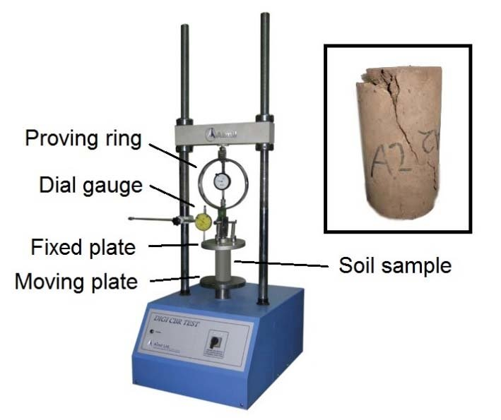
(a) Load frame to apply compressive load at constant rate of strain
(b) Proving Ring
(c) Dial gauge
(d) Vernier calipers
(e) Bearing plates
(f) Trimmer, sample extractor, constant volume mould with plungers
Specimen Size:
Minimum diameter: 35 mm
Height to diameter ratio = 2
3. Theory:
In this test, a cylinder of soil, without lateral support, is tested to failure in simple compression, at constant rate of strain. The compressive load per unit area required to fail the soil cylinder is called the " unconfined compressive strength " of the soil. Half of this is taken as the shear strength of the soil. The test is applicable for cohesive soil.
4. Preparation of Specimens:
A. Undisturbed Specimen
(i) Remove the protective cover (paraffin wax) from the sample.
(ii) Place the sampling tube in the sample extractor and push the plunger till a small length of sample comes out.
(iii) Cut out this projected sample using a wire saw.
(iv) Again push the plunger of the extractor till a 7.6 cm long sample comes out.
(v) Cut out this sample carefully and hold it so that it does not fall.
(vi) Measure the diameter at the top, middle and bottom of the sample and find the average and record.
(vii) Measure the height accurately and record.
(viii) Find the weight and record.
5. Procedure:
(i) Place the specimen on the base plate of the load frame.
(ii) Keep a bearing plate with a ball seating groove on the top of the specimen.
(iii) Place a hardened steel ball on the bearing plate.
(iv) Fix the proving ring to the load frame such that it transfer the load from the frame to the ball and it turn to the specimen.
(v) Make final adjustments to ensure that the load is applied axially to the specimen.
(vi) Fix a dial gauge to measure the vertical compression of the specimen.
(vii) Adjust the gear position on the load frame to give a strain rate of 1.25 mm/minute.
(viii) Start applying the load and record the readings on the proving ring dial and compression dial every 30 seconds.
(ix) Continue loading till cracks have developed on the specimen or till the specimen has compressed by 1.5 cm.
(x) Stop loading and take the specimen out of the load frame.
(xi) Sketch the failure pattern.
(xii) Measure the angle between the horizontal and the cracks
6. Observation Table:
Initial Diameter (Do) : --------------------
Initial Length (Lo) : ----------------------
Area of cross section (Ao): π/4 . Do^2
Observation Table:
Time Compression Dial Reading Strain(∈) Corrected Area Proving Ring reading Axial load
(minutes) (mm) ∆L/L Ac = Ao/(1- ∈) (Div.) P (kg)
0 ------- ------- ------- ------- -------
0.5 ------- ------- ------- ------- -------
1.0 ------- ------- ------- ------- -------
1.5 ------- ------- ------- ------- -------
2.0 ------- ------- ------- ------- -------
2.5 ------- ------- ------- ------- -------
3.0 ------- ------- ------- ------- -------
3.5 ------- ------- ------- ------- -------
4.0 ------- ------- ------- ------- -------
4.5 ------- ------- ------- ------- -------
5.0 ------- ------- ------- ------- -------
5.5 ------- ------- ------- ------- -------
6.0 ------- ------- ------- ------- -------
Compressive stress = P/Ac
Unconfined compressive strength: --------------------
Shear strength of soil : -------------------
Consistency of the soil : ------------------
7. Standard Value:
Wednesday, 27 April 2022
California Bearing Ratio (CBR) Test
1. Aim:
To determine the California Bearing Ratio of the soil subgrade.
2. Theory:
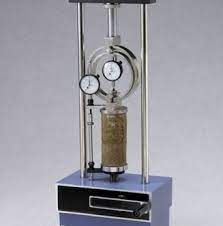
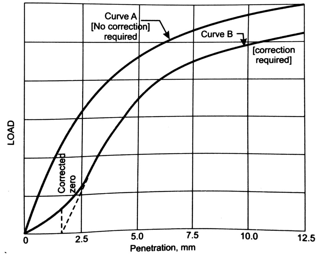
CBR test originally developed by California Division Highways (USA) is one of the most commonly used methods to evaluate the strength of subgrade soil for design of pavement thickness. CBR value as defined by IS: 2720 (Part XVI)-1979 is the ratio of the force per unit area required to penetrate a soil mass with a circular plunger of 50 mm diameter at the rate of 1.25 mm/minute, to that required for corresponding penetration of a standard material. Standard load ( 1370 kg for 2.5 mm penetration and 2055 kg for 5.0 mm) is the load which has been obtained from tests on a crushed stone whose CBR value is taken to be 100%. The ratio is usually determined for penetration of 2.5 mm and 5.0 mm. The results of this test can be related accurately with fundamental properties of the material but are useful in design of flexible pavements.
3. Apparatus Used:
(a) Mould: A metallic (Gun metal or steel) cylinder of 150 mm internal diameter and 175 mm height; provided with a detachable metal extension collar 50 mm in height. It also has a detachable perforated base plate of 10 mm thickness. The perforation in the base plate do not exceed 1.5 mm in diameter.
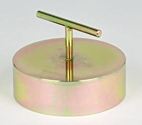
(b) Spacer Disc: A metal disc of 148 mm diameter and 47.7 mm in height. The spacer disc has groove on one side so that a handle can be screwed to facilitate its lifting.
(c) Surcharge weight: One annular metal weight and slotted weight of 2.5 kg and 147 mm in diameter with a central hole 53 mm in diameter.
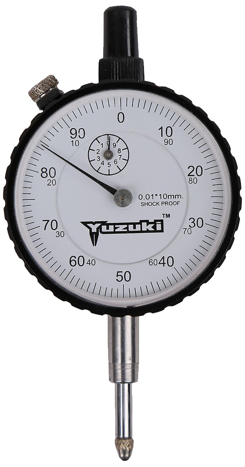
(d) Dial gauges: 2 dial gauges required
(e) IS sieves of size 4.75 mm and 20 mm
(f) Penetration Plunger: A metallic plunger having a diameter of 50 mm and at least 100 mm long.
(g) Loading Machine with a capacity of at least 5000 kg and equipped with a platform that can move vertically @ 1.25 mm/minute.
(h) Proving ring of capacity 5000 kg
(i) Other apparatus like mixing bowl, straight edge, scale, filter paper and measuring jar.
4. Procedure
(i) Sieve the material through 20 mm IS sieve.
(ii) Take about 5.5 kg soil.
(iii) Add water to the soil in the quantity such that the moisture content of the specimen is either equal to field moisture content or OMC desired.
(iv) Mix soil with water uniformly.
(v) Clamp the mould along with the extension collar to the base plate.
(vi) Place the spacer disc in the mould and put a coarse filter paper on top of it. The hole should be on bottom side.
(vii) Pour soil-water mix in the mould in such a quantity the after compaction about 1/3rd (for light compaction) or 1/5th (for heavy compaction) of the mould is filled.
(viii) Give 55 blows with a rammer weighing 2.6 kg, dropping through 310 mm in 3 layers (light compaction) or 4.90 kg, dropping through 450 mm in 5 layers (heavy compaction)
(ix) Scratch the top layer of compacted surface. Add more soil and compact in similar fashion.
(x) Remove the extension collar and trim off the excess soil by a straight edge.
(xi) Remove the base plate, spacer disc and the filter paper and note down the weight of mould and compacted specimen.
4.1. CBR Test on Soaked Specimen:
Prepare the specimen and follow as below:
(i) Weigh the sample excluding base plate and spacer disc.
(ii) Place a filter paper is on the sample with a perforated plate on it.
(iii) Place over it surcharge weight 2.5 to 5.0 kg and soak the sample in water tank for 4 days.
(iv) Allow to drain off water from the sample in a vertical position for 15 minutes.
(v) Weigh the sample again to calculate the percentage of water absorbed.
(vi) Then test the sample following the normal procedure.
5. Testing the Specimen:
(i) Place the mould containing the specimen, with base plate in position, on the testing machine.
(ii) Place the annular weight of 2.5 kg on the top surface of soil.
(iii) Fix the proving ring assembly and penetration plunger on the loading machine
(iv) Bring the penetration plunger in contact with soil surface and apply a seating load of 4 kg so that full contact between soil and plunger is established. This should be taken as zero load.
(v) Place the remaining surcharge weight (slotted weight) so that total surcharge weight equals to 5.0 kg.
(vi) Fix the dial gauge with the tip of its stem resting on the collar to measure the penetration.
(vii) Set the reading of dial gauges to zero.
(viii) Apply load so that penetration rate is 1.25 mm/minute. Record the load at penetration of 0, 0.5, 1, 1.5, 2, 2.5, 4, 5, 7.5, 10 and 12.5 mm. In case load reading starts decreasing before 12.5 mm penetration, record the maximum load and the corresponding penetration value.
(ix) Collect about 20 to 50 g soil from the top to determine the water content.
At least 3nspecimens should be tested on each type of sample.
6. Computation of Test Results
(i) Plot the load penetration curve with load as ordinate and penetration as abscissa. Sometimes the initial portion of the curve is concave upwards due to surface irregularities. In such a case apply a correction. Draw tangent at the point of greatest slope. The point where this tangent meets the abscissa is the corrected zero reading of penetration.
(ii) From the curve, determine the load value corresponding to the penetration value at which the CBR is desired.
(iii) Compute CBR value as follows:
CBR (in %) = Test load corresponding to chosen penetration x 100 / Standard load for the same penetration
Usually CBR value at 2.5 mm penetration will be greater than that at 5.0 mm penetration. Generally the CBR value at 2.5 mm penetration will be greater than that at 5.0 mm penetration and in such a case the former is taken for design purposes. If the 5.0 mm value is greater, the test is repeated. If the same results follow, the CBR value corresponding to 5.0 mm penetration is adopted for design purposes.
Standard Load for different penetration values :
Penetration (in mm) Total Standard Load (kg) Standard Pressure (kg/cm2)
2.5 1370 70
5.0 2055 105
7. Observation:
Type of sample : Undisturbed/ Remoulded
Compaction : Static/ Dynamic
Type of compaction : Light/Heavy
Condition of soaking: Soaked/ Unsoaked
Period of soaking : ----------- hour
Surcharge weight : -------------
Observation Table:
Penetration (mm) No of divisions on proving ring Corresponding load (kg)
0 ------------- ------------
0.5 ------------- -------------
1.0 ------------- -------------
1.5 ------------- -------------
2.0 ------------- -------------
2.5 ------------- -------------
4.0 ------------- -------------
5.0 ------------- -------------
7.5 ------------- -------------
10.0 ------------- -------------
12.5 ------------- -------------
CBR at 2.5 mm penetration = --------------------
CBR at 5 mm penetration = ---------------------------
8. Standard Value:
Soil Type CBR (%)
Well graded gravel (GW) 40-80
Poorly graded gravel (GP) 30-60
Silty Gravel (GM) 40-60
Clayey Gravel (GC) 20-40
Well graded sand (SW) 20-40
Poorly graded sand (SP) 10-40
Silty sand (SM) 10-40
Clayey sand (SC) 5-20
ML or MI <15
CH <15
MH < 10
Organic soil < 5
HAPPY LEARNING
Please follow me on https://talktorashid.blogspot.com/
Saturday, 16 April 2022
Environmental Engineering
👉 Domestic demand = 135 lpcd (liter per capita per day)
Public demand = 20 lpcd
Industrial demand = 50 lpcd
Commercial demand = 20 lpcd
Fire demand = 15 lpcd
Loss and waste = 50 lpcd
Total demand = 270 lpcd
👉 IS code says Domestic water consumption between 135 to 225 lpcd
School/colleges : 45 to 135 lpcd
Offices : 45 lpcd
Restaurants : 70 lpcd
Cinema : 15 lpcd
Hotels : 180 lpcd
Hospitals : 340 lpcd
👉 Water treatment design period = 15 years
Pipe connection to the several treatment units = 30 years
Distribution system = 30 years
👉 As per GOI manuals
Characteristics Acceptable Cause for Rejection
Total Hardness (as CaCO3) (mg/l) 200 600
Nitrates (mg/l) 45 45
Iron (mg/l) 0.1 1.0
Fluorides (mg/l) 1.0 1.5
👉 The maximum safe-limits in domestic water supply are
Sulphates ≤ 200 mg/l
Chloride ≤ 250 mg/l
Nitrates ≤ 45 mg/l
Fluorides ≤ 1.5 mg/l
👉 Carbonate hardness = min of { Total Hardness or Alkalinity
👉 Total dissolved solids (TDS) content of water supply can be obtained by specific conductance measurements i.e., the electrical conductivity of water.
👉 Chloride content of water is computed by Mohr's method
👉 Chlorine residual can be computed by following tests:
(a) Orthotolidine test
(b) Starch iodide test
(c) DPD test
(d) Chlorotex test
👉 Temporary Hardness: Carbonates and bicarbonates of Ca and Mg.
Alkalinity and softness: Carbonate and bicarbonates of sodium (Na)
Permanent Hardness: Sulphates and chlorides of of Ca and Mg
👉Pseudo hardness is given by monovalent cations like sodium (Na+)
👉 The Winkler test is used to determine the concentration of dissolved oxygen (DO) in water.
👉 Miscellaneous Topic:
Friday, 25 March 2022
Irrigation Engineering
👉 Garret's diagram is used to design channels.
👉Garret's diagram is a graphical representation to obtain canal design parameters based on
- Kennedy's Theory
- Kutter's formula
Lacey's design is based on stable channels in alluvium and he assumed some bed load and suspended load.
1. True Regime
2. Initial Regime
3. Final Regime
👉 True Regime: A channel is said to be in regime condition if it is transporting water and sediment in equilibrium such that there is neither silting nor scouring of the channel. But according to Lacey, the channel should satisfy the following conditions to be in regime condition.
- Channel is said to be in initial regime condition when only the bed slope of channel gets affected by silting and scouring and other parameters are independent even in non-silting and non-scouring velocity condition.
- It may be due to the absence of incoherent alluvium.
- According to Lacey’s, regime theory is not applicable to initial regime condition.
- If the channel parameters such as sides, bed slope, depth etc. are changing according to the flow rate and silt grade then it is said to be in final regime condition.
- The channel shape may vary according to silt grade
Step1: Compute Lacey Silt Factor (f)
d = average size of particle in mm
Here V = Velocity of flow in m/sec
Q = Discharge in m3/sec
f = Lacey's silt factor
Step 3: Compute Area of the Channel by using
Q = A.V
Step 4: Compute wetted perimeter (P) of the channel
Here, P is the wetted perimeter in m
Q is the discharge in m3/sec
Step 5: Compute Hydraulic radius (R)
Here R is the hydraulic radius in m
V is the velocity in m/sec
f is the silt factor
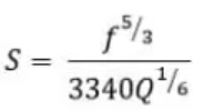
Step 6: Compute Bed slope (S) by Lacey theory as
Note: Lacey Regime Scour depth (R) can be computed as
- Lacey did not explain the properties that govern the alluvial channel.
- In general, flow is different at bed and sides of the channel which requires two different silt factors but Lacey derived only one silt factor.
- The semi-elliptical shape proposed by Lacey as the ideal shape of the channel is not convincing.
- Lacey did not consider the
silt concentration in his equations. - Attrition of silt particles is ignored by Lacey.
- Lacey did not give proper definitions for the silt grade and silt charge.
HAPPY LEARNING
👉 Follow me on talktorashid.blogspot.com


