Saturday, 30 April 2022

Determination of Unconfined Compressive Strength Test (UCS Test of soil)

 1. Objective:

To determine the unconfined compressive strength of soil 

2. Apparatus Used:

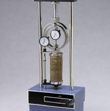
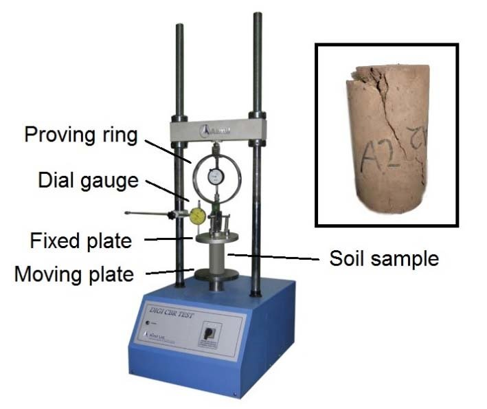
(a) Load frame to apply compressive load at constant rate of strain

(b) Proving Ring

(c) Dial gauge 

(d) Vernier calipers

(e) Bearing plates

(f) Trimmer, sample extractor, constant volume mould with plungers

Specimen Size:

Minimum diameter: 35 mm

Height to diameter ratio  = 2

3. Theory: 

In this test, a cylinder of soil, without lateral support, is tested to failure in simple compression, at constant rate of strain. The compressive load per unit area required to fail the soil cylinder is called the " unconfined compressive strength " of the soil. Half of this is taken as the shear strength of the soil. The test is applicable for cohesive soil.

4. Preparation of Specimens: 

A. Undisturbed Specimen

(i) Remove the protective cover (paraffin wax) from the sample.

(ii) Place the sampling tube in the sample extractor and push the plunger till a small length of sample comes out.

(iii) Cut out this projected sample using a wire saw.

(iv) Again push the plunger of the extractor till a 7.6 cm long sample comes out.

(v) Cut out this sample carefully and hold it so that it does not fall.

(vi) Measure the diameter at the top, middle and bottom of the sample and find the average and record.

(vii) Measure the height accurately and record.

(viii) Find the weight and record.

5. Procedure:

(i) Place the specimen on the base plate of the load frame.

(ii) Keep a bearing plate with a ball seating groove on the top of the specimen.

(iii) Place a hardened steel ball on the bearing plate.

(iv) Fix the proving ring to the load frame such that it transfer the load from the frame to the ball and it turn to the specimen.

(v) Make final adjustments to ensure that the load is applied axially to the specimen.

(vi) Fix a dial gauge to measure the vertical compression of the specimen.

(vii) Adjust the gear position on the load frame to give a strain rate of 1.25 mm/minute.

(viii) Start applying the load and record the readings on the proving ring dial and compression dial every 30 seconds.

(ix) Continue loading till cracks have developed on the specimen or till the specimen has compressed by 1.5 cm.

(x) Stop loading and take the specimen out of the load frame.

(xi) Sketch the failure pattern.

(xii) Measure the angle between the horizontal and the cracks


6. Observation Table:

Initial Diameter (Do) : --------------------

Initial Length (Lo) : ----------------------

Area of cross section (Ao): Ο€/4 . Do^2

Observation Table:

 Time      Compression Dial Reading     Strain(∈)    Corrected Area   Proving Ring reading    Axial load

(minutes)               (mm)                            ∆L/L             Ac =  Ao/(1- ∈)         (Div.)                   P (kg)

    0                       -------                           -------                 -------                      -------                  -------

   0.5                     -------                           -------                 -------                      -------                  -------

   1.0                      -------                           -------                 -------                      -------                  -------

   1.5                     -------                           -------                 -------                      -------                  -------

   2.0                     -------                           -------                 -------                      -------                  -------

   2.5                    -------                           -------                 -------                      -------                  -------

  3.0                      -------                           -------                 -------                      -------                  -------

  3.5                      -------                           -------                 -------                      -------                  -------

  4.0                     -------                           -------                 -------                      -------                  -------

  4.5                     -------                           -------                 -------                      -------                  -------

  5.0                     -------                           -------                 -------                      -------                  -------

  5.5                     -------                           -------                 -------                      -------                  -------

  6.0                     -------                           -------                 -------                      -------                  -------


Compressive stress  = P/Ac

Unconfined compressive strength: --------------------

Shear strength of soil : -------------------

Consistency of the soil : ------------------

7. Standard Value:


Wednesday, 27 April 2022

California Bearing Ratio (CBR) Test

1. Aim:

To determine the California Bearing Ratio of the soil subgrade.

 2. Theory: 

CBR test originally developed by California Division Highways (USA) is one of the most commonly used methods to evaluate the strength of subgrade soil for design of pavement thickness. CBR value as defined by IS: 2720 (Part XVI)-1979 is the ratio of the force per unit area required to penetrate a soil mass with a circular plunger of 50 mm diameter at the rate of 1.25 mm/minute, to that required for corresponding penetration of a standard material. Standard load ( 1370 kg for 2.5 mm penetration and 2055 kg for 5.0 mm) is the load which has been obtained from tests on a crushed stone whose CBR value is taken to be 100%. The ratio is usually determined for penetration of 2.5 mm and 5.0 mm. The results of this test can be related accurately with fundamental properties of the material but are useful in design of flexible pavements. 

3. Apparatus Used: 

(a) Mould: A metallic (Gun metal or steel) cylinder of 150 mm internal diameter and 175 mm height; provided with a detachable metal extension collar 50 mm in height. It also has a detachable perforated base plate of 10 mm thickness. The perforation in the base plate do not exceed 1.5 mm in diameter.


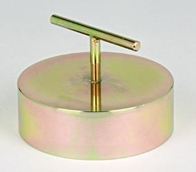
(b) Spacer Disc: A metal disc of 148 mm diameter and 47.7 mm in height. The spacer disc has groove on one side so that a handle can be screwed to facilitate its lifting.


(c) Surcharge weight: One annular metal weight and slotted weight of 2.5 kg and 147 mm in diameter with a central hole 53 mm in diameter.


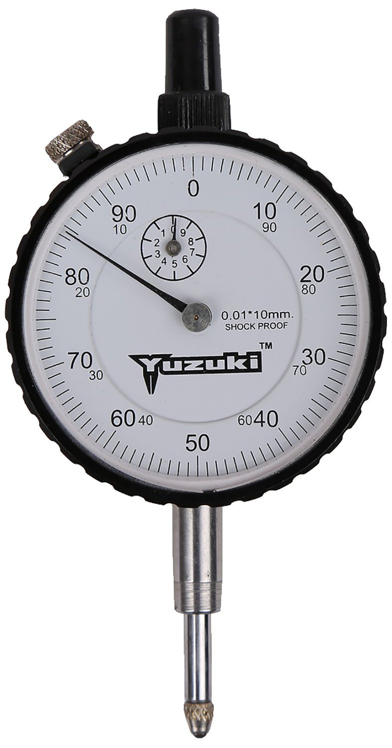
(d) Dial gauges: 2 dial gauges required


(e) IS sieves of size 4.75 mm and 20 mm


(f) Penetration Plunger: A metallic plunger having a diameter of 50 mm and at least 100 mm long.

(g) Loading Machine with a capacity of at least 5000 kg and equipped with a platform that can move vertically @ 1.25 mm/minute.

(h) Proving ring of capacity 5000 kg

(i) Other apparatus like mixing bowl, straight edge, scale, filter paper and measuring jar.

4. Procedure

(i) Sieve the material through 20 mm IS sieve.

(ii) Take about 5.5 kg soil.

(iii) Add water to the soil in the quantity such that the moisture content of the specimen is either equal to field moisture content or OMC desired.

(iv) Mix soil with water uniformly.

(v) Clamp the mould along with the extension collar to the base plate.

(vi) Place the spacer disc in the mould and put a coarse filter paper on top of it. The hole should be on bottom side.

(vii) Pour soil-water mix in the mould in such a quantity the after compaction about 1/3rd (for light compaction) or 1/5th (for heavy compaction) of the mould is filled.

(viii) Give 55 blows with a rammer weighing 2.6 kg, dropping through 310 mm in 3 layers (light compaction) or 4.90 kg, dropping through 450 mm in 5 layers (heavy compaction)

(ix) Scratch the top layer of compacted surface. Add more soil and compact in similar fashion.

(x) Remove the extension collar and trim off the excess soil by a straight edge.

(xi) Remove the base plate, spacer disc and the filter paper and note down the weight of mould and compacted specimen.

4.1. CBR Test on Soaked Specimen:

Prepare the specimen and follow as below:

(i) Weigh the sample excluding base plate and spacer disc.

(ii) Place a filter paper is on the sample with a perforated plate on it.

(iii) Place over it surcharge weight 2.5 to 5.0 kg and soak the sample in water tank for 4 days.

(iv) Allow to drain off water from the sample in a vertical position for 15 minutes.

(v) Weigh the sample again to calculate the percentage of water absorbed.

(vi) Then test the sample following the normal procedure.

5. Testing the Specimen:

(i) Place the mould containing the specimen, with base plate in position, on the testing machine.

(ii) Place the annular weight of 2.5 kg on the top surface of soil.

(iii) Fix the proving ring assembly and penetration plunger on the loading machine

(iv) Bring the penetration plunger in contact with soil surface and apply a seating load of 4 kg so that full contact between soil and plunger is established. This should be taken as zero load.

(v) Place the remaining surcharge weight (slotted weight) so that total surcharge weight equals to 5.0 kg.

(vi) Fix the dial gauge with the tip of its stem resting on the collar to measure the penetration.

(vii) Set the reading of dial gauges to zero.

(viii) Apply load so that penetration rate is 1.25 mm/minute. Record the load at penetration of 0, 0.5, 1, 1.5, 2, 2.5, 4, 5, 7.5, 10 and 12.5 mm. In case load reading starts decreasing before 12.5 mm penetration, record the maximum load and the corresponding penetration value.

(ix) Collect about 20 to 50 g soil from the top to determine the water content.

At least 3nspecimens should be tested on each type of sample. 


6. Computation of Test Results

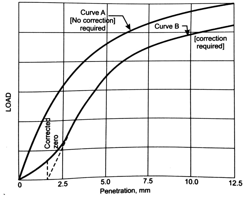
 (i) Plot the load penetration curve with load as ordinate and penetration as abscissa. Sometimes the initial portion of the curve is concave upwards due to surface irregularities. In such a case apply a correction. Draw tangent at the point of greatest slope. The point where this tangent meets the abscissa is the corrected zero reading of penetration.


(ii) From the curve, determine the load value corresponding to the penetration value at which the CBR is desired.

(iii) Compute CBR value as follows:

  CBR (in %) = Test load corresponding to chosen penetration x 100 / Standard load for the same penetration


Usually CBR value at 2.5 mm penetration will be greater than that at 5.0 mm penetration. Generally the CBR value at 2.5 mm penetration will be greater than that at 5.0 mm penetration and in such a case the former is taken for design purposes. If the 5.0 mm value is greater, the test is repeated. If the same results follow, the CBR value corresponding to 5.0 mm penetration is adopted for design purposes. 

Standard Load for different penetration values :

Penetration (in mm)                   Total Standard Load (kg)                  Standard Pressure (kg/cm2)

       2.5                                                        1370                                                      70

       5.0                                                        2055                                                     105


7. Observation:

 Type of sample     :          Undisturbed/ Remoulded

Compaction           :           Static/ Dynamic

Type of compaction :   Light/Heavy

Condition of soaking: Soaked/ Unsoaked

Period of soaking :      ----------- hour

Surcharge weight :    -------------

Observation Table:

   Penetration (mm)            No of divisions on proving ring       Corresponding load (kg)  

          0                                           -------------                                            ------------  

         0.5                                         -------------                                            -------------       

         1.0                                          -------------                                             -------------       

         1.5                                          -------------                                            -------------       

        2.0                                            -------------                                            -------------       

        2.5                                             -------------                                           -------------       

        4.0                                              -------------                                          -------------       

        5.0                                             -------------                                            -------------       

        7.5                                              -------------                                             -------------       

        10.0                                             -------------                                             -------------       

       12.5                                              -------------                                              -------------       


 CBR at 2.5 mm penetration = --------------------

CBR at 5 mm penetration = ---------------------------

8. Standard Value:

       Soil Type                                                         CBR (%)

Well graded gravel (GW)                                           40-80

Poorly graded gravel (GP)                                          30-60

Silty Gravel (GM)                                                       40-60

Clayey Gravel (GC)                                                    20-40

Well graded sand (SW)                                               20-40

Poorly graded sand (SP)                                              10-40

Silty sand (SM)                                                            10-40

Clayey sand (SC)                                                          5-20

ML or MI                                                                       <15

CH                                                                                  <15

MH                                                                                 < 10

Organic soil                                                                    < 5


                                                       HAPPY LEARNING

                              Please follow me on https://talktorashid.blogspot.com/


Saturday, 16 April 2022

Environmental Engineering

 πŸ‘‰ Domestic demand = 135 lpcd (liter per capita per day)

        Public demand   = 20 lpcd

         Industrial demand = 50 lpcd

         Commercial demand = 20 lpcd

         Fire demand = 15 lpcd

         Loss and waste = 50 lpcd 

          Total demand = 270 lpcd

πŸ‘‰ IS code says Domestic water consumption between 135 to 225 lpcd

      School/colleges : 45 to 135 lpcd

     Offices : 45 lpcd

     Restaurants : 70 lpcd

     Cinema : 15 lpcd

     Hotels : 180 lpcd

     Hospitals : 340 lpcd

πŸ‘‰  Water treatment design period = 15 years

        Pipe connection to the several treatment units = 30 years

       Distribution system = 30 years

πŸ‘‰ As per GOI manuals 

     Characteristics                                        Acceptable                 Cause for Rejection  

    Total Hardness (as CaCO3) (mg/l)                  200                                    600

   Nitrates (mg/l)                                                    45                                       45

    Iron     (mg/l)                                                     0.1                                      1.0

  Fluorides (mg/l)                                                  1.0                                      1.5

πŸ‘‰ The maximum safe-limits in domestic water supply are

      Sulphates   ≤  200 mg/l

     Chloride      ≤  250 mg/l 

    Nitrates        ≤  45 mg/l

    Fluorides     ≤  1.5 mg/l

πŸ‘‰ Carbonate hardness = min of { Total Hardness or Alkalinity

πŸ‘‰ Total dissolved solids (TDS) content of water supply can be obtained by specific conductance measurements i.e., the electrical conductivity of water.

πŸ‘‰ Chloride content of water is computed by Mohr's method

 πŸ‘‰ Chlorine residual can be computed by following tests:

    (a) Orthotolidine test

    (b) Starch iodide test

    (c) DPD test

    (d) Chlorotex test

πŸ‘‰ Temporary Hardness: Carbonates and bicarbonates of Ca and Mg.

       Alkalinity and softness: Carbonate and bicarbonates of sodium (Na)

       Permanent Hardness: Sulphates and chlorides of of Ca and Mg

 πŸ‘‰Pseudo hardness is given by monovalent cations like sodium (Na+)

πŸ‘‰ The Winkler test is used to determine the concentration of dissolved oxygen (DO) in water.

πŸ‘‰ Miscellaneous Topic: 

Miscellaneous Topic EE-I